- Whatsapp: 8618958900507
- Email: [email protected]


In a fluid transportation pipeline system, branch connectors are basically the weakest part of the structure. Among them, the pipe cross joint (four – way splitter) is a core component that has to bear pressure from multiple directions, forces caused by thermal expansion and contraction, and continuous fluid impact during operation.
If the wall thickness of the pipe cross joint doesn’t match well with that of the connected straight pipe, there’ll be structural discontinuity at the welding position, which will lower the efficiency of force transmission. This problem won’t show up right away. Instead, it’ll gradually turn into a safety hazard during the long – term operation of the pipeline.
This article, combined with the Pandapipe pipeline wall thickness design logic in the industry, briefly explains the method of matching the wall thickness between the pipe cross joint and the pipeline. I’m gonna give a full explanation of the harms of unmatched wall thickness, standardized matching rules, formulas for calculating wall thickness, on – site construction optimization techniques, and ways to handle common problems. This’ll help engineers effectively avoid stress concentration at the pipe intersections and achieve the best balance among pipeline operation safety, service life, and project cost.
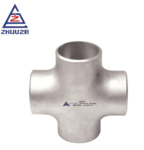
v When there’s a big difference in wall thickness between the cross pipe fitting, an obvious step will form at the weld. At this time, the internal pressure and axial tension of the pipeline can’t be transmitted smoothly, and all the stress will concentrate at the weld.
In this situation, the locally concentrated stress can be 2 to 4 times the normal stress of the pipeline. Especially for high – pressure oil, gas, and chemical pipelines, the requirements for stress are extremely strict. Once the stress exceeds the limit, weld leakage is very likely to happen during the hydrostatic test, or it may even lead to cracking directly.
If the pipe intersection is thicker while the pipeline is thinner, the thin – walled pipeline will be over – stretched. On the contrary, if the pipe intersection is thinner and the pipeline is thicker, the opening of the pipe fitting will deform. Both combinations don’t meet the ASME B31.3 industrial pipeline design standard and are considered illegal construction.
Most industrial pipelines operate under cyclic conditions for a long time: pressure fluctuations, thermal expansion and contraction of the pipeline, and continuous vibration of the pump. These factors make the pipe joints bear stress repeatedly.
At the pipe intersections, if the wall thickness is inconsistent, these alternating stresses will be continuously amplified, accelerating the fatigue damage of the pipeline and significantly shortening the overall designed service life of the pipeline.
According to on – site measurement results, if the wall – thickness transition isn’t optimized, small cracks usually appear at the pipe intersections with unmatched wall thickness within 3 to 5 years of operation. Under the continuous action of corrosive media, these small cracks will expand rapidly and eventually lead to pipeline failure. By reasonably matching the wall thickness and eliminating stress concentration, this common hidden danger can be fundamentally solved.
All standard cross pipe fittings on the market use a unified international wall – thickness system, including SCH40, SCH80, SCH160, and XXS (extra – thick) specifications. They fully comply with two major industry standards: ASME B16.9 and GB/T12459.
Daily choices usually fall into two situations:
The first is four – way pipe fittings with the same diameter and the same wall thickness. The wall thicknesses of the four ports are exactly the same. They’re suitable for general operating conditions and can achieve uniform flow distribution in the pipeline system.
The second is four – way pipe fittings with different diameters and variable wall thicknesses. Their wall thicknesses vary according to the actual pressure difference between the main pipeline and the branch pipes. The key is that each port of the four – way pipe fitting must be individually matched with the wall – thickness specification of the corresponding pipeline.
There’s a strict requirement: The designed wall thickness of the four – way pipe fitting must not be less than that of the connected straight pipe. If thin – walled pipes are needed for the project, direct butt – welding is not allowed. Instead, custom – made four – way joints with a transition structure must be used to avoid structural stress defects.
When it’s impossible to achieve exactly the same wall thickness during the installation process, three core and practical standards should be followed to ensure correct matching:
Prioritize wall – thickness uniformity
For medium – and low – pressure conventional applications, four – way pipe fittings that exactly match the pressure rating and wall – thickness specification of the pipeline should be selected to eliminate potential stress problems caused by wall – thickness differences at the source.
Strictly control the maximum wall – thickness difference
If a wall – thickness difference is unavoidable, the difference between the port of the four – way joint and the connected pipeline should not exceed 1.5 mm. Professional transitional grinding must be carried out before welding. Direct welding is strictly prohibited.
Give priority to transitional processing of thicker parts
When the wall thickness is mismatched, the end of the thicker part should always be processed and ground to form a smooth and gradual slope. Don’t try to force the installation by reducing the wall thickness of the thin – walled pipe, or it may cause eccentric loads at the weld and lead to stress – related risks.
The pressure – bearing wall thickness of each branch port of a four – way pipe fitting can’t be estimated just based on experience. In the industry, the general wall – thickness calculation formula in the official pipeline design standards of Pandapipe is commonly used as the core reference for wall – thickness matching and pressure design of all industrial four – way pipe fittings.
T = \frac{P×D}{2(SEW + PY)} + C
Parameter definition:
T: Calculated pressure-bearing wall thickness of cross branch end (mm)
P: Pipeline design pressure (MPa)
D: Pipe outer diameter (OD)
S: Material allowable stress
E: Weld factor (seamless cross E=1.0, welded cross E=0.6–0.85)
W: Temperature derating factor, default 1.0
Y: Steel material constant, approximately 0.4
C: Basic corrosion allowance
| Allowance Code | Type | Value Reference | Application Scenario |
| c₁ | Mechanical machining allowance | 1.0 mm | Threaded cross end, bevel cutting loss |
| c₂ | Corrosion allowance | 1–3 mm | Acidic, saline corrosive medium transport |
| c₃ | Erosion allowance | 0.5–1.0 mm | Medium containing solid particles |
After calculating the theoretical minimum wall thickness of the pipe fitting, there’s no need to randomly choose the type. You can directly refer to the national standard SCH series specifications and select the standard four – way pipe fitting that is closest to and not less than the calculated value, so as to achieve an accurate wall – thickness match.

Just choosing the appropriate wall thickness is not enough to completely solve the stress concentration problem at four – way joints. On – site transition treatment and construction details are also important.
According to the requirements of the ASME UW – 9(c) specification, when the wall – thickness difference between the pipe fitting and the pipeline exceeds 1.5 mm, direct welding is prohibited. A tapered transition treatment must be adopted. The specific construction methods are as follows:
Conventional slope transition
Process it with a uniform slope of 1:3. The transition grinding length should be at least three times the wall – thickness difference. Only grind the outer wall of the thicker pipe fitting to form a smooth and gradual slope, so that the stress can be smoothly transferred.
Double – sided transition treatment for high – pressure thick – wall pipes
For high – pressure and thick – wall industrial pipelines, both the inner and outer walls need to be processed to ensure uniform wall thickness at the welded joint position, thus avoiding uneven local stress in the structure.
Installing reinforcing gaskets to enhance the reinforcement effect
Under extremely harsh working conditions such as ultra – high pressure, circular reinforcing gaskets can be installed at the four – way joint position. This can effectively increase the pressure – bearing thickness of the interface, significantly reduce the stress concentration coefficient, and ensure the long – term stable operation of the pipeline.
Before welding, use an ultrasonic thickness gauge to measure the actual wall thickness of the four – way port and the connecting pipeline respectively. This can compensate in advance for the manufacturing tolerance errors when the product leaves the factory and avoid problems caused by specification parameter deviations during construction.
Give priority to custom – made pre – transition pipe fittings
If the pipeline specifications are diverse and the wall thicknesses vary, directly purchasing pre – transition joints with pre – fabricated transition ends can greatly reduce on – site grinding processes, thereby improving construction efficiency and ensuring more stable quality.
Reasonably adjust the welding sequence
During construction, joints with the same wall thickness and no wall – thickness difference should be welded first, and then the interfaces that need transition grinding should be processed. Avoid forced alignment and hard – pulling alignment to prevent internal stress during assembly.
Non – destructive testing after welding
After all welding is completed, conduct ultrasonic (UT) and magnetic particle (MT) non – destructive testing on the four – way welds to detect hidden micro – cracks caused by stress concentration and prevent potential problems such as leakage and cracking during subsequent operation.
Can a SCH40 cross fitting be directly welded to a SCH80 straight pipe without any treatment?
Absolutely not recommended. The wall thickness difference between the two specifications is quite large. After welding, there will be an obvious step at the joint, and the pipe will continuously generate fatigue stress, posing a long – term safety hazard. The correct way is to chamfer and grind the end of the SCH80 thick pipe according to a standard taper of 1:3, or directly choose a cross fitting with a built – in transition structure.
How much corrosion allowance should be reserved for cross fittings used to transport chemical media?
There is no fixed value for the corrosion allowance. It needs to be calculated based on the corrosion rate of the medium and the designed service life of the pipe. For common acidic chemical media, usually reserving 2 – 3 millimeters is enough. And this corrosion thickness must be included in the overall wall – thickness matching design of the cross fitting in advance and cannot be added later.
What tool can be used to detect the actual wall thickness of the cross joint after the pipeline installation is completed?
The most commonly used tool in the industry is the ultrasonic thickness gauge. It has high detection accuracy, with the error controlled within ±0.1 millimeter. It can not only detect the actual wall thickness after installation but also is suitable for long – term monitoring of pipeline corrosion and wall – thickness loss.
Will the pipe fitting brand affect the matching accuracy of the cross joint wall thickness?
It will have a significant impact. Products from standardized and well – reputed brands have stricter tolerances. ZHIJU manufactures strictly in accordance with international wall – thickness tolerance standards. The port sizes of its cross fittings are uniform and highly accurate, which can greatly reduce the on – site grinding and transition processing work and provide a more flexible and reliable solution.
To completely solve the stress concentration problem of pipe cross joints, precisely matching the wall thickness is the most core and effective method. Whether it’s the early – stage risk assessment, pipe fitting specification selection, wall – thickness formula calculation, or on – site transition processing and construction, every step must follow a standardized process. This can effectively avoid safety accidents such as weld cracking and pipeline leakage caused by the inconsistency between the pipe fitting and the pipeline wall – thickness structure.
Mastering the complete wall – thickness design, calculation methods, and construction techniques can reduce the fatigue damage of cross joints from the source, effectively extend the service life of the entire pipeline system, and significantly reduce the later – stage maintenance and repair costs.
Based on the mature standardized production process, ZHIJU cross fittings fully comply with international wall – thickness matching specifications and are suitable for various industrial fluid transportation conditions, providing a stable and reliable safety structure guarantee for the pipeline system. If your project needs a customized wall – thickness solution for cross fittings, a comparison of specification parameters, or on – site matching technical guidance, please feel free to consult our professional engineering team. We’ll provide you with a one – stop pipeline and pipe fitting compatibility solution.

THE QUALITY IS THE SOUL OF AN ENTERPRISE
Zhejiang Zhiju Pipeline Industry Co., Ltd
Official Website: https://www.zhiju-steel.com
Privacy Policy
Copyright ZHEJIANG ZHIJU PIPELINE INDUSTRY CO., LTD SUPPORT BY :JUNJ
 Optimized by Seraphinite Accelerator